Do you like this site? Remember to share it to all your friends on Facebook and Twitter!

Monday, December 28, 2009

IOS "show clock" results' heading symbols

 R0>show clock
 *00:20:29.467 UTC Fri Mar 1 2002 
 R0>
We all know by "show clock" command we can know the system time on an IOS host. Do you notice there are some symbols ahead of the result output? Here is my research:
Reference of show clock on Cisco.com


Table 15 show clock Display Leading Symbol Descriptions

Symbol

Description

*

Time is not authoritative.

(blank)

Time is authoritative.

.

Time is authoritative, but NTP is not synchronized.


* NOTE: the above table also applies to log messages!

Friday, December 4, 2009

How can you forget these IP addresses: "8.8.8.8" and "8.8.4.4"?

 Primary DNS: 8.8.8.8 
 Secondary DNS: 8.8.4.4 
How can you forget the following IP addresses: "8.8.8.8" and "8.8.4.4"?

It is Google's public DNS resolvers.

Thursday, December 3, 2009

VoIP: simple proof of IP network's quality

Suppose that some remote colleague were complaining about the application performance, and she were assuming "IP network performance" is to blame.

If I could call back by phone and explain to her: "I am calling over the same IP network. What do you think about the voice quality right now?!"

Isn't this quite a simple proof of IP network's quality! I now have a good purpose to implement telephony services on IP networks!

Monday, October 19, 2009

MAC address ranges of virtualized world

Nowadays when several MAC addresses are associated with one switch port, we cannot assume that this port is connected to another switch or hub as before. It might be connected to a Virtual Machine server.

Friday, October 16, 2009

Wi-Fi Blocking Paint

We know that Wireless LAN (Wi-Fi) is riding on non-licensed bands of radio frequencies. It is unavoidable, especially in a metropolitan area, that our facilities are filled with un-wanted wireless LAN radios.

With new strong encryption, we do not have to worry about the information leakage. However, we DO have to worry about effective transmission throughput. The more users in the same channels, the less effective throughput can we get!

Tuesday, October 6, 2009

How to verify the Secondary Root?

As you know  we can configure the designated switch as the "Primary root role" or the "Secondary root role" using the following commands:
spanning-tree vlan 10 root primay
spanning-tree vlan 20 root secondary
  
Although these commands are just "macros" that we cannot see them in the running configuration, it is still easy to verify the "Primary root role" is correctly configured: We just use "show spanning-tree" command to check the designated switch is really the current "Root Bridge".

Tuesday, September 22, 2009

Why a "vlan.dat" file for an IOS switch?

It looks to me the "vlan.dat" design will stay a long life on IOS switches.

Saturday, September 19, 2009

How to remove VTP domain string: 2 reloads

To restore a IOS switch to a "whole new" state, it is necessary to clear even the "VTP domain" string to null. I thought at first just remove "vlan.dat" followed by a reload would do it, but now I found that I was NOT quite correct!

Saturday, September 12, 2009

Binary and Decimal number conversion practice

 153 =  1    0    0    1    1    0    0    1 
       ---  ---  ---  ---  ---  ---  ---  ---  
       128   64   32   16   8    4    2    1 

       2^7  2^6  2^5  2^4  2^3  2^2  2^1  2^0 
We must be skillful enough about conversions between binary and decimal number when we are learning IP address and subnet mask writing. It would be especially helpful if we have a self-practice environment.

Sunday, August 30, 2009

CCNA Exploration 4.0 Companion Packet Tracer Practices, the Collection

I collect all my "CCNA Exploration 4.0 Companion Packet Tracer Practice" links of old posts here.

You can just bookmark this post to browse them all at once. Enjoy them!

Wednesday, August 12, 2009

RAM Suggestions for most BGP Routers

Although my post provides a rough estimation about how much RAM could a BGP router take (70M bytes for 100,000 routes), I would like to suggest you to buy the maximum size of RAM of your router model in your deployment.

Sunday, August 9, 2009

Number of BGP routes comes up to 300,000

I came across this post: "BGP breaks 300,000". Applying my previous rough estimation: 70M bytes for 100,000 routes, it would takes around 210M bytes to only store that 300,000 BGP routes in memory alone!

Monday, August 3, 2009

BGP Memory Requirement, Estimation

I was asked about how to estimate the memory requirement for a BGP implementation. I found this page on Cisco.com could be a good source for us making this estimation.
The article in fact is about techniques to minimize the memory consumption of a BGP implementation. However, the table on the "Conclusion" section answers my question:


Number of Prefixes

Memory Consumed

No Filtering

98,410

70,882,248

Autonomous System Filter

31,667

28,132,528

Well, if this table is true, I can easily tell a BGP table with 100,000 entries would takes around 70 Megabytes.

One of my friends confirms it is a good estimation on his BGP router. Is this estimation also working for you? Please share with me!

[Reference]
"Achieve Optimal Routing and Reduce BGP Memory Consumption" on Cisco.com

Wednesday, July 29, 2009

"Rough cuts" of "CCIE Routing and Switching Exam Certification Guide, 4th Edition"

I was studying the 3rd Edition of "CCIE Routing and Switching Exam Certification Guide". Now comes the "Rough Cuts" of the 4th Edition!

Rough cuts?! I thought at the first glance the 4th Edition was already available. In fact, it is not! The explanation on the same page of this book says:

What is a Rough Cut?

The Rough Cuts service from Safari Books Online gives you exclusive access to an evolving manuscript that you can read online or download as a PDF and print. A Rough Cuts book is not fully edited or completely formatted, but you'll get access to new versions as they are created.

To dig further by clicking "Buy from Safari Books Online", I found this book is estimated to be published on November 06, 2009.

Interesting! Let's wait for it until the coming November!

Monday, July 27, 2009

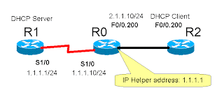
IP Helper Address: what about "Source Address" of the diverted broadcast packets?

I crafted an sample "IP Helper Address" lab, and I found the "Source Address" of the diverted broadcast packets should be the unicast address of the interface which enabled "IP Helper Address".

The demonstration output capture is this:
  1. When no "Helper" is enabled, all DHCP broadcasts (DISCOVERY) are just ignored.
  2. Enabling "Helper". Note about the IP address (2.1.1.10) of this LAN interface and the configured diversion destination address (1.1.1.1)
  3. From this time on, the debug output shows the DHCP broadcast's source address is changed from "0.0.0.0" to "2.1.1.10", and destination address is changed from "255.255.255.255" to "1.1.1.1". The packet is forwarded to DHCP server (R1).
  4. Then, DHCP server's response (OFFER) packet is sourced from "1.1.1.1" to destination "2.1.1.10", as expected.
  5. The "Helper" relays it to the client and changes the source address of the packet from "1.1.1.1" to its own address: "2.1.1.10", also the destination is changed from "2.1.1.10" to "255.255.255.255", as if the response were generated from itself.

R0#show ip int brief
Interface                  IP-Address      OK? Method Status                Protocol
FastEthernet0/0            unassigned      YES unset  up                    up      
FastEthernet0/0.200        2.1.1.10        YES manual up                    up      
FastEthernet0/1            unassigned      YES unset  administratively down down    
Serial1/0                  1.1.1.10        YES manual up                    up      
Serial1/1                  unassigned      YES manual administratively down down    
Serial1/2                  unassigned      YES unset  administratively down down    
Serial1/3                  unassigned      YES unset  administratively down down    
R0#
*Mar  1 00:42:43.599: IP: s=0.0.0.0 (FastEthernet0/0.200), d=255.255.255.255, len 604, rcvd 2
*Mar  1 00:42:47.111: IP: s=0.0.0.0 (FastEthernet0/0.200), d=255.255.255.255, len 604, rcvd 2
*Mar  1 00:42:51.159: IP: s=0.0.0.0 (FastEthernet0/0.200), d=255.255.255.255, len 604, rcvd 2
R0#conf t
Enter configuration commands, one per line.  End with CNTL/Z.
R0(config)#int f0/0.200
R0(config-subif)#ip helper-address 1.1.1.1
R0(config-subif)#end
R0#
*Mar  1 00:43:07.607: %SYS-5-CONFIG_I: Configured from console by console
*Mar  1 00:43:09.239: IP: s=0.0.0.0 (FastEthernet0/0.200), d=255.255.255.255, len 604, rcvd 2
*Mar  1 00:43:09.255: IP: tableid=0, s=2.1.1.10 (local), d=1.1.1.1 (Serial1/0), routed via FIB
*Mar  1 00:43:09.259: IP: s=2.1.1.10 (local), d=1.1.1.1 (Serial1/0), len 604, sending
*Mar  1 00:43:09.439: IP: tableid=0, s=1.1.1.1 (Serial1/0), d=2.1.1.10 (FastEthernet0/0.200), routed via RIB
*Mar  1 00:43:09.443: IP: s=1.1.1.1 (Serial1/0), d=2.1.1.10, len 328, rcvd 4
*Mar  1 00:43:09.459: IP: s=2.1.1.10 (local), d=255.255.255.255 (FastEthernet0/0.200), len 328, sending broad/multicast
*Mar  1 00:43:09.567: IP: s=0.0.0.0 (FastEthernet0/0.200), d=255.255.255.255, len 604, rcvd 2
*Mar  1 00:43:09.583: IP: tableid=0, s=2.1.1.10 (local), d=1.1.1.1 (Serial1/0), routed via FIB
*Mar  1 00:43:09.587: IP: s=2.1.1.10 (local), d=1.1.1.1 (Serial1/0), len 604, sending
*Mar  1 00:43:09.619: IP: tableid=0, s=1.1.1.1 (Serial1/0), d=2.1.1.10 (FastEthernet0/0.200), routed via RIB
*Mar  1 00:43:09.623: IP: s=1.1.1.1 (Serial1/0), d=2.1.1.10, len 328, rcvd 4
*Mar  1 00:43:09.635: IP: s=2.1.1.10 (local), d=255.255.255.255 (FastEthernet0/0.200), len 328, sending broad/multicast
R0#
R0#

I now have a conclusion: the "ip helper address" must have been WRONGLY described in this book: Wendell Odom, Rus Healy, Naren Mehta."CCIE Routing and Switching Exam Certification Guide, 3rd Edition", Page 128 and also Page 134!

Sunday, July 19, 2009

VTP Password can be shown!

I did not notice that we can use "show" commands to display the VTP (VLAN Trunking Protocol) password!

I was reminded by my student these days. We can see this document "Configuring VTP Global Parameters" for a sample.

Switch#show vtp password
VTP Password:WATER
Switch#

I should have known this in CCNA courses. How careless I am!

Monday, July 13, 2009

VTP Explained in Animation, on Cisco.com

I came across this Flash animation explaining VLAN Trunking Protocol (VTP), right on Cisco.com.

It is very clear and fully explaining many details about VTP. I believe it would help you to understand VTP even further!
http://www.cisco.com/warp/public/473/vtp_flash/

Enjoy it!

Saturday, June 27, 2009

Dual Stack IPv6 and IPv4 configuration (CNA-04-006)

CCNA Exploration 4.0, Semester 4, "Dual Stack IPv6 and IPv4 configuration " Packet Tracer 5.0 practice file (CNA-04-006).


This example is designed for you to practice basic IPv6 commands in IOS. You will also know the new fashion to start a routing protocol in IPv6.

Note: Packet Tracer 4.X does not support IPv6. Please use version 5.X and later to practice IPv6.

To simplify your task, I configured all the necessary IPv4/IPv6 addresses on the interfaces. You can just begin to observe and verify!


interface FastEthernet0/0
 ip address 10.1.1.1 255.255.255.0
 duplex auto
 speed auto
!
interface FastEthernet0/1
 no ip address
 duplex auto
 speed auto
 ipv6 address 2001:1:1:1::1/64
!
interface Serial0/0/0
 ip address 10.2.2.1 255.255.255.0
 ipv6 address 2001:2:2:2::1/64
 clock rate 64000
!

You have to configure "routing protocol" yourself. To verify "Dual Stack", we will enable both IPv4 routing protocol and IPv6 routing protocol.

The IPv4 part (in this case, RIPv2) is very easy for you. Remember the basic two steps to start any IPv4 routing protocols in IOS:

  1. Use one "router X" command, to start one routing protocol process
  2. Use one or more "network Y" commands, to specify at which interfaces will this protocol being enabled

So the configuration is this:

router rip
 version 2
 network 10.0.0.0
 no auto-summary
!

For this simple IPv4 addressing, it is not necessary to include an "no auto-summary" command. It is always a good habit to add "no auto-summary" in today's VLSM world.

As to IPv6 part (RIPng), steps are quite different from IPv4:

  1. We need to start the routing protocol process first. In addition, we also have to create a TAG name for it. This is because in IPv6 IOS supports multiple instances on routing protocols
  2. Go directly to interface configuration mode to assign which "routing instance" to be enabled on this interface.


interface FastEthernet0/1
 no ip address
 duplex auto
 speed auto
 ipv6 address 2001:1:1:1::1/64
 ipv6 rip CCNA enable 
!
interface Serial0/0/0
 ip address 10.2.2.1 255.255.255.0
 ipv6 address 2001:2:2:2::1/64
 ipv6 rip CCNA enable 
 clock rate 64000
!
interface Serial0/0/1
 no ip address
 shutdown
!
ipv6 router rip CCNA
!

In fact, the tag name "CCNA" is only locally significant. You can play by using different tags on two routers and verify it yourself.

Friday, June 5, 2009

How to describe 2^128, the total number of IPv6 addresses

I like the way described on Wiki about 2128, the total number of IPv6 addresses:
... approximately 5×1028 (roughly 295) addresses for each of the roughly 6.5 billion (6.5×10⁹) people alive in 2006. ...

You will get a share of "astronomical" number of addresses in IPv6: 5×1028. I believe it is impressive enough for us all to imagine how large the number is!

I also found an interesting page questioning the correctness of some bold statements about this number, such as "IPv6 will let us individually address every proton on earth" or "the number of possible IPv6 addresses will be larger than the number of molecules in the universe".

I think this analysis is correct, so I won't use such statements anymore!

Tuesday, June 2, 2009

Configure NAT/PAT to enable outbound Internet connectivity (CNA-04-005)

CCNA Exploration 4.0, Semester 4, "Configure NAT/PAT to enable outbound Internet connectivity" Packet Tracer 5.0 practice file (CNA-04-005).


The diagram is the same as the previous post, except that EIGRP between Router R0 and Router R1 is removed, and a new default route pointing to R0 (here it represents the Internet) has been added into R1.

Before we start to configure NAT/PAT, we can easily verify that any PCs or Switches below R1 cannot connect to R0. This is because R0 does not have any route to those network addresses (192.168.X.0/24) below R1. We must successfully configure NAT/PAT to translate all source IP addresses into those in network 10.1.1.0/24 to achieve outbound connectivity to R0 (Internet).

Recall that the 3 basic steps to configure NAT/PAT:

  1. Specify "Inside" interfaces: source addresses of packets coming through these interfaces need to be translated
  2. Specify Outside interfaces: destination addresses of packets coming through these interfaces need to be recovered
  3. Define translation rule: this step is quite different between NAT and PAT. I will discuss PAT and NAT in different sections later

Step 1 and 2 are all the same in all modes:
interface FastEthernet0/0
 ip address 192.168.10.1 255.255.255.0
 ip nat inside
 duplex auto
 speed auto
!
interface FastEthernet0/1
 ip address 192.168.11.1 255.255.255.0
 ip nat inside
 duplex auto
 speed auto
!
interface Serial0/0/0
 ip address 10.1.1.1 255.255.255.0
 ip nat outside
 clock rate 64000
!

[PAT]

The only difference is at Step 3. Let's start from PAT.

PAT enable us to reuse the IP address of Router R1's "Serial0/0/0" interface for all inside hosts. Since every host is translated into the same IP address, we can only tell which packets should be recovered to which source host by its TCP/UDP port number.

Now, we need ACL here again! We use ACL to classify packets. If the classification result is permit, then it will be translated; otherwise if the result is deny, it will NOT be translated.

Key configuration fragment is as below:


ip nat inside source list 100 interface Serial0/0/0 overload
!
access-list 100 permit ip 192.168.10.0 0.0.0.255 any
access-list 100 permit ip 192.168.11.0 0.0.0.255 any
!

Here is the translation result of PAT. NOTE: If you want to see similar results as I do, you must create some connections outbound to R0, such as TELNET. The screen capture is done when 2 PCs are having 2 active TELNET sessions to Router R0.

R1>show ip nat translation
Pro  Inside global     Inside local       Outside local      Outside global
tcp 10.1.1.1:1024      192.168.10.10:1025 10.1.1.2:23        10.1.1.2:23
tcp 10.1.1.1:1025      192.168.11.10:1025 10.1.1.2:23        10.1.1.2:23

R1>

We can see clearly the effect of PAT on Router R0. R0 thought it was 2 connections sourced from 10.1.1.1.

R0>show user
    Line       User       Host(s)              Idle       Location
* 67 vty 0                idle                 00:00:00 10.1.1.1
  68 vty 1                idle                 00:01:48 10.1.1.1

  Interface    User               Mode         Idle     Peer Address
R0>

[NAT]

In NAT, each local IP address will occupy one public global address when we configure NAT instead. Here I assume IP addresses from 10.1.1.101 to 10.1.1.200 is reserved as a pool for NAT use.

NOTE: IP address pool here is similar to car parking slot pool. One car, one slot, and in "first-come-first-serve" way. In above example, only the first 100 local hosts making outbound connections will get its own address. If the pool is full, starting from 101st late comer, no new local hosts can be served by NAT and thus cannot make outbound connections at all!

Key configuration fragment is as below:

ip nat pool INET-POOL 10.1.1.101 10.1.1.200 netmask 255.255.255.0
ip nat inside source list 100 pool INET-POOL
!
access-list 100 permit ip 192.168.10.0 0.0.0.255 any
access-list 100 permit ip 192.168.11.0 0.0.0.255 any
!

The screen capture is done as before when 2 PCs are having 2 active TELNET sessions to Router R0.

R1>show ip nat translation
Pro  Inside global     Inside local       Outside local      Outside global
---  10.1.1.101        192.168.10.10      ---                ---
---  10.1.1.102        192.168.11.10      ---                ---

R1>

The effect of NAT is clearer on Router R0. R0 thought they were connecting from 10.1.1.101 and 10.1.1.102.

R0>show users
    Line       User       Host(s)              Idle       Location
*  0 con 0                idle                 00:00:00 
  67 vty 0                idle                 00:01:45 10.1.1.101
  68 vty 1                idle                 00:01:35 10.1.1.102

  Interface    User               Mode         Idle     Peer Address
R0>

Sunday, May 31, 2009

Using Access Control List (ACL) to restrict inbound Internet access (CNA-04-004)

CCNA Exploration 4.0, Semester 4, "Using Access Control List (ACL) to restrict inbound Internet access" Packet Tracer 5.0 practice file (CNA-04-004).


In this example, I design on purpose to ask you: you must allow PING (that is, ICMP) and disallow TELNET (that is, TCP port 23) at the same time. So that you will be forced to use "Extended" ACL. This is because we have to us one ACL to allow and disallow packets in different services from the same source IP address, which is not possible in "Standard" ACL.

A sample content of ACL and its application could be like this:

interface Serial0/0/0
 ip address 10.1.1.1 255.255.255.0
 ip access-group 100 in
 clock rate 64000
!
access-list 100 deny tcp any 192.168.0.0 0.0.255.255 eq telnet
access-list 100 permit ip any any

The above sample assumes you apply it on the inbound direction of "Serial0/0/0". We can also apply the same ACL on the outbound direction of "FastEthernet0/0" and "FastEthernet0/1" to achieve the same protection.

Also remember: the question in a test about ACL always have been framed into one possible answer. In daily life, there is often more than one possible answer to your asked requirements. Be creative about the possible outcome answer for ACL!

Monday, May 25, 2009

Using TFTP to recover Cisco IOS Image file, and to backup/restore configurations (CNA-04-003)

CCNA Exploration 4.0, Semester 4, "Using TFTP to recover Cisco IOS Image file, and to backup/restore configurations" Packet Tracer 5.0 practice file (CNA-04-003).


This Packet Tracer file is only a simple environment for you to "experience" using TFTP to recover Cisco IOS Image file, and to backup/restore configurations.

However, if you have access to physical real router/switch, especially when you are in a training course, do not waste your chance of practicing! Packet Tracer,as a simulator, is absolutely not comparable to real machines!

For example, it does not simulate all Cisco IOS behaviors. The following Packet Tracer screen captures shows many command option is still missing from the real Cisco 2960 switch.

[In Packet Tracer 5.0]


Cisco-Switch-2960>en
Cisco-Switch-2960#copy ?
  running-config  Copy from current system configuration
  startup-config  Copy from startup configuration
  tftp:           Copy from tftp: file system
Cisco-Switch-2960#copy tftp: ?
  flash:          Copy to flash: file system
  running-config  Copy configuration from system
  startup-config  Copy startup configuration from system
Cisco-Switch-2960#

[In real Cisco 2960 switch]


Cisco-Switch-2960#copy ?
  /erase          Erase destination file system.
  /noverify       Disable automatic image verification after copy
  bs:             Copy from bs: file system
  cns:            Copy from cns: file system
  flash:          Copy from flash: file system
  ftp:            Copy from ftp: file system
  null:           Copy from null: file system
  nvram:          Copy from nvram: file system
  rcp:            Copy from rcp: file system
  running-config  Copy from current system configuration
  startup-config  Copy from startup configuration
  system:         Copy from system: file system
  tftp:           Copy from tftp: file system
  xmodem:         Copy from xmodem: file system
  ymodem:         Copy from ymodem: file system

Cisco-Switch-2960#copy tftp: ?
  flash:          Copy to flash: file system
  null:           Copy to null: file system
  nvram:          Copy to nvram: file system
  running-config  Update (merge with) current system configuration
  startup-config  Copy to startup configuration
  system:         Copy to system: file system

Cisco-Switch-2960#

Repeat: simulator is not a replacement of real machine at all!

Friday, May 22, 2009

Frame Relay and RIP problem configuration and observation (CNA-04-002)

CCNA Exploration 4.0, Semester 4, "Frame Relay and RIP problem configuration and observation" Packet Tracer 5.0 practice file (CNA-04-002).


Of course, I do not recommend you to use RIP anymore during my lecture. Since this is a typical RIP over Frame Relay problem in all versions of ICND materials, you might be interested to configure and observe it!

In this example, we have only two Virtual Circuit available. One is between Router 1 and Router 2, and the other is between Router 2 and Router 3. This is quite a typical deployment in "hub and spoke" scenario to minimize virtual circuit cost!

The access to Frame Relay configuration is not difficult at all for you. All you have to do is to change serial encapsulation to "frame-relay". Here is the sample configuration for Router 1:


interface Serial0/0/0
 ip address 10.1.1.1 255.255.255.0
 encapsulation frame-relay

After you configure all three interfaces on three routers, please wait a moment! Cisco IOS's Inverse ARP feature would automatically setup the correct IP addresses mapping to DLCIs. We can examine this on Router 2:


R2#show frame-relay map
Serial0/0/0 (up): ip 10.1.1.1 dlci 201, dynamic, broadcast, CISCO, status defined, active
Serial0/0/0 (up): ip 10.1.1.3 dlci 203, dynamic, broadcast, CISCO, status defined, active
R2#ping 10.1.1.1

Type escape sequence to abort.
Sending 5, 100-byte ICMP Echos to 10.1.1.1, timeout is 2 seconds:
!!!!!
Success rate is 100 percent (5/5), round-trip min/avg/max = 40/50/60 ms

R2#ping 10.1.1.3

Type escape sequence to abort.
Sending 5, 100-byte ICMP Echos to 10.1.1.3, timeout is 2 seconds:
!!!!!
Success rate is 100 percent (5/5), round-trip min/avg/max = 40/54/91 ms

R2#

The frame relay access portion is actually done! Now we look closer at the RIP problem.

After we start RIP on all routers with default setting, we will immediately see a serious problem: Router 1 does not receive Router 3's RIP routes, and vice versa.

R1>show ip route
Codes: C - connected, S - static, I - IGRP, R - RIP, M - mobile, B - BGP
       D - EIGRP, EX - EIGRP external, O - OSPF, IA - OSPF inter area
       N1 - OSPF NSSA external type 1, N2 - OSPF NSSA external type 2
       E1 - OSPF external type 1, E2 - OSPF external type 2, E - EGP
       i - IS-IS, L1 - IS-IS level-1, L2 - IS-IS level-2, ia - IS-IS inter area
       * - candidate default, U - per-user static route, o - ODR
       P - periodic downloaded static route

Gateway of last resort is not set

     10.0.0.0/24 is subnetted, 1 subnets
C       10.1.1.0 is directly connected, Serial0/0/0
C    192.168.1.0/24 is directly connected, FastEthernet0/0
R    192.168.2.0/24 [120/1] via 10.1.1.2, 00:00:23, Serial0/0/0
R1>

The cause for this on Router 2. We have only two virtual circuits available in this case. Therefore, only Router 2 will receive Router 3's RIP updates. Router 1 will never receive them unless Router 2 re-send those RIP updates for Router 1.

Recall the default behavior of "split horizon": both Router 1 and Router 3 are addressed in the same subnet, so any RIP updates received in Router 2's Serial0/0/0 interface connecting to this subnet will not be re-sent out through the same interface Serial0/0/0 by Router 2!

That is why Router 1 will not receive Router 3's updates, because Router 2 won't re-send them!

To eliminate this problem, we have to disable the "split horizon" function on Router 2's Serial0/0/0, like this:

interface Serial0/0/0
 ip address 10.1.1.2 255.255.255.0
 no ip split-horizon
 encapsulation frame-relay

Then RIP goes well with such Frame Relay deployment and addressing!

I want to repeat this over and over to you: this is only a sample problem of RIP on Frame Relay. I strongly suggest you to use better protocols such as EIGRP or OSPF instead. Both of them does not have such odd "split horizon" problem. You should refer to this only if you cannot remove RIP in your network!

Thursday, May 21, 2009

Configuring PPP on serial interfaces and CHAP Authentication (CNA-04-001)

CCNA Exploration 4.0, Semester 4, "Configuring PPP on serial interfaces and CHAP Authentication" Packet Tracer 5.0 practice file (CNA-04-001).


This is a simple practice for you to change the layer 2 encapsulation from defautl HDLC to PPP. And the reference answer file also contains sample CHAP authentication configurations.

You can also read my previous post so you won't get confused about the username/password and directions.

Wednesday, May 20, 2009

PPP with CHAP Authentication, Quick Reference


Quick reference for PPP together with CHAP authentication configuration.

hostname Left
username Right password samepassword

int serial 1/0
encapsulation ppp
ppp authentication chap
ip address 1.1.1.1 255.255.255.0
no shutdown


hostname Right
username Left password samepassword

int serial 1/0
encapsulation ppp
ppp authentication chap
ip address 1.1.1.2 255.255.255.0
no shutdown

Tuesday, May 19, 2009

Client PC's Redundancy: Wireless LAN, also backup Internet's traffic

Continued from previous post. Have you come up with the answer?

The key is still the "more specific route": we only have to craft some routes more specific than the "default route"! The default route itself is indeed the least specific! Any routes with just one bit more specific, is enough to be more specific!

---

OK! Let me give you the answer: we only have to add two routes 0.0.0.0/1128.0.0.0/1, pointing both of them to Wired LAN's gateway IP address, done! Now the Internet traffic will go through Wired LAN in normal time. It goes through the Wireless LAN only when Wired LAN is broken!

Why these 2 routes? We can clearly see it by looking at its binary form:

33          2          1          0       33          2          1          0
1098765.43210987.65432109.876543210       1098765.43210987.65432109.876543210

00000000.00000000.00000000.00000000, mask 10000000.00000000.00000000.00000000

10000000.00000000.00000000.00000000, mask 10000000.00000000.00000000.00000000

Of course, we can also come up with 4 routes, or even 8 routes to play the same trick! Two is the simplest one!

Interesting, isn't it! This trick is quite useful in many cases! We might see it again very often!

Sunday, May 17, 2009

Client PC's Redundancy: Wireless LAN

Yellow Flowers (DSCN0947)
Yellow Flowers (DSCN0947),
originally uploaded by Li-Ji.
To provide Client PCs with network backup redundancy, Wireless LAN has a unique advantage that all Wired LAN cannot provide at all: Automatic Recovery! Windows will do this by itself to find another available "Access Point", automatically! That's why I emphasize Automatic Recovery: user will not even notice the network has been down for a moment because of single network device's failure, when all the client PCs use Wireless LAN only to connect to the network!

However, Wireless LAN today still has it technical limitation of "Bandwidth". This problem would become more serious if client PCs are located densely close to each other, and each client PC runs applications consuming lots of bandwidth. Using Wireless LAN only on client PC would now be a nightmare for network administrators, if the client PCs should be arranged in this way!

I have another suggestion for you. We can use Wireless LAN as a backup redundancy to Wired LAN, so we can take both technology's benefit at the same time. In the normal scenario the whole traffic goes through Wired LAN. Once the Switch fails, client PCs divert traffic to Wireless LAN for backup. Although at this backup time the network would still be slow because of Wireless LAN's limitation, at lease we can still keep full connectivity to all client PCs.

Can the switchover be automatic, too? Sure! The trick is to make use of "more specific routes"! Assume the Intranet is within the "192.168.0.0/16" range. We first separate both Wired LAN and Wireless LAN into different network of addressing. Then we point the route to "192.168.0.0/255.255.0.0" on Windows to the gateway IP address of Wired LAN, and point the "default route" to the gateway IP address on Wireless LAN side.

You see it! In normal time traffic would go through more specific route through Wired LAN. Only when Wired LAN is down would traffic go through Wireless LAN. Automatically done!

As how to add those two routes in client PCs, we can make use of Window's AD Group Policy. Or even simpler, we just use DHCP to insert the two routes into client PCs.

I believe some of you might come up with another question: this solution only solves the "Intranet" automatic back redundancy. How about the traffic to the Internet?

The trick is very similar. Let me take a breath and you keep watching my blog! I will tell you in my next post!

Friday, May 15, 2009

Redundancy: a great lesson to me!

I believe many you have noticed about some .PKT files and some .JPG files cannot be downloaded or viewed since one day ago. In fact, a serious down time is happening to me my ONLY web hosting provider.

Their attendant of customer service of this provider said they are doing some emergency recovery, and are doing their best, but no ETA (I guess it is Estimated Time of Available)! As the time of this post, the service is still not recover yet! It is already over 24 hours and breaking their 99.9% up time promise!

I have to say sorry for your patience! Because I did not backup some of my important files, some contents would take longer to recover!

I always preached to my students about redundancy in network design . However, I did not do with my contents under this discipline. This time I am having a great (and painful) lessen to me!

Thursday, May 14, 2009

Provide across 3 VLANs, Layer 3 connectivity using a router with single LAN interface (CNA-03-007)

CCNA Exploration 4.0, Semester 3, "Provide across 3 VLANs, Layer 3 connectivity using a router with single LAN interface" Packet Tracer 5.0 practice file (CNA-03-007).


What?! Single one LAN interface to service 3 VLANs? Yes, no problem! We only have to configure it with new commands we have not learned!

Remember that in a trunk connection among switches, we have to "tag" every frame so switches can tell which frame belongs to which VLAN. If a router can also recognize and add the same tags just like switches, we can make this router "virtually" connect to all the VLANs on the switches, and thus providing across VLAN routing, using single physical LAN interface!

We usually call such router a nick name: "Router on a stick". That is, a (LAN) router with only one interface (leg)!

Since VLAN tagging is a hardware functionality, we have to remember in mind that not all routers and not all LAN interface card can support this function: router's LAN interface has to be at least 100Mbps (FastEthernet, in Cisco's term). If your router is bought recently, such as the new ISR (Integrated Service Routers) models, then this requirement is quite enough.

Our "Router on a stick" routes packets among sub-interfaces. Each sub-interface stands for a logical (virtual) interface plugged in a VLAN. The configuration is like this:


interface FastEthernet0/0
 no ip address
 duplex auto
 speed auto
!
interface FastEthernet0/0.100
 encapsulation dot1Q 10
 ip address 172.17.10.1 255.255.255.0
!
interface FastEthernet0/0.200
 encapsulation dot1Q 20
 ip address 172.17.20.1 255.255.255.0
!
interface FastEthernet0/0.300
 encapsulation dot1Q 30
 ip address 172.17.30.1 255.255.255.0
!

The numbers after "encapsulation dot1q 10", "encapsulation dot1q 20", and "encapsulation dot1q 30" are exactly the VLAN's ID number, used in 802.1Q tagging.

However, the number of sub-interface has no special meaning at all. I intentionally choose different sub-interface numbers (100, 200, 300) from VLAN numbers in this example.

We also have to do some configuration on switch side. We have to configure the switch port connected to the router as "Trunk mode". Router needs this to receive and send frames from and to different VLANs.

interface FastEthernet0/11
 switchport mode trunk
!

"Router on a stick" in fact solves one additional problem: scalability. No matter across how many VLANs we have to route packets, we always need only one physical LAN interface!

Consider this then you will see the problem: suppose we have to provide routing among 100 VLANs and without this function, we would be in serious trouble finding a router with 100 LAN interfaces!

Wednesday, May 13, 2009

Provide across 3 VLANs, Layer 3 connectivity using a router with 3 LAN interfaces (CNA-03-006)

CCNA Exploration 4.0, Semester 3, "Provide across 3 VLANs, Layer 3 connectivity using a router with 3 LAN interfaces" Packet Tracer 5.0 practice file (CNA-03-006).


Previous practices we are separating PCs into different VLANs. In this practice we are going to connect them together instead using Layer 3 router!

Because only 3 VLANs, we only have to prepare a router with 3 LAN interfaces.

It wont' be difficult for you if you have get through Semester 2 well. You only have to make sure each switch ports the router's interfaces connecting to is in the same VLAN as those PCs they service. Of course, the 3 inter-switch link should also be enabled as "Trunk Link".

You can use this practice as a review of Semester 2's knowledge!

Tuesday, May 12, 2009

Using TELNET to backup Cisco Router and Switch's configuration

Aboriginal Art and Ponds, in Hualian County, Taiwan
I believe you agree that you hardly attach a console cable to your routers or switches in daily maintenance. Your network devices are always locked up on a rack in a room so far away! TELNET is a more frequently used software on Windows.

To backup configuration of a Cisco router or switch, I share with you a tip using TELNET. (However, this tip is only applicable on Windows XP!) If your PC comes with Windows Vista or 7, you should install TELNET client first.

Monday, May 11, 2009

Collections of my companion practice added, right second panel

Yes! I am posting a series of Packet Tracer files I prepared for my students in Cisco Network Academy. For you to find them all quickly, I listed them in the right second panel of this blog.

I believe it would be very helpful for both network students and even instructors!

I have not posted them all yet! Keep watching the coming posts!

You are welcome to use all these file as you wish! And please do not hesitate to give me your feedback!

Sunday, May 10, 2009

Observe and configure designated switch as Spanning Tree Protocol's root role (CNA-03-005)

CCNA Exploration 4.0, Semester 3, "Observe and configure designated switch as Spanning Tree Protocol's root role" Packet Tracer 5.0 practice file (CNA-03-005).


It will not be difficult for you to maintain VLAN connectivity for both VLAN 10 and VLAN 20. We have four previous examples. Practice 1, Practice 2, Practice 3, and Practice 4.

This practice is focused on the root role switch of a Spanning Tree Protocol domain.

How important is the root role switch? Because all broadcast frames in that VLAN would go through the root role switch. That is, if your root role switch's performance is modest, you will absolutely have poor network performance as a whole.

Practically, we usually choose the best performance switch (maybe also the most expensive switch!) as the root role in a Spanning Tree Protocol domain.

Root role is automatic selected according to the Spanning Tree Protocol. If all switches are using default Spanning Tree configuration, the root role is almost "randomly" chosen, because switch with the smallest MAC addresses (treat that MAC address as a long hexadecimal number) will be elected as root role.

See below the "show spanning-tree" result on "S2". It is the elected root role switch for VLAN 1.

S2#show spanning-tree 
VLAN0001
  Spanning tree enabled protocol ieee
  Root ID    Priority    32769
             Address     0002.4AEE.B73B
             This bridge is the root
             Hello Time  2 sec  Max Age 20 sec  Forward Delay 15 sec

  Bridge ID  Priority    32769  (priority 32768 sys-id-ext 1)
             Address     0002.4AEE.B73B
             Hello Time  2 sec  Max Age 20 sec  Forward Delay 15 sec
             Aging Time  20

Interface        Role Sts Cost      Prio.Nbr Type
---------------- ---- --- --------- -------- --------------------------------
Fa0/1            Desg FWD 19        128.1    P2p
Fa0/2            Desg FWD 19        128.2    P2p
Fa0/6            Desg FWD 19        128.6    P2p
Fa0/11           Desg FWD 19        128.11   P2p
Fa0/18           Desg FWD 19        128.18   P2p

S2#

In this practice, if we want to designate S1 as the root for VLAN 10, and S3 as the root for VLAN 20, we can issue the following commands on respective switches:

(These commands are the few exceptions of commands that won't be listed in the running-config. You have to use "show spanning-tree" command instead to observe!)

S1(config)# spanning-tree vlan 10 root primary

S3(config)# spanning-tree vlan 20 root primary

I believe you would guess there should be a "secondary" command of the same form. Exactly! This secondary command is for us to designate "backup switch" for the root role. When the root role switch dies, it will take over to be the new root role switch.

In this example we assume we also want S1 to be the backup for VLAN 20, and S3 to be the backup for VLAN 10, as root role switch. The we should issue the following commands:

S1(config)# spanning-tree vlan 20 root secondary

S3(config)# spanning-tree vlan 10 root secondary

We can use these commands to choose which switch to be the primary root role, and which switch to be the backup (secondary) root role, as the way we want!

Friday, May 8, 2009

How to get thourgh the economic slow down? You can spend more time to learn!

Open wide and full (DSCN0634)
Open wide and full (DSCN0634),
originally uploaded by Li-Ji.
I believe many people, no matter in what business, or suffering in any condition, would absolutely have more and more "free time"!

From the brighter side of view, it is a great chance for you to "learn"! I would like to give your some advices:

  1. You can spend more time on the Cisco Learning Network. It is a Cisco Official site and so many peoplpe are gathering around discussing and sharing information there about learning and certification.
  2. You may invest yourself, or find sponsorship from your company, to enroll some good training courses. For example, try to type "ccnp course" in the "Google Custom Search" box above every post in my blog to find some good CCNP-related training courses.
  3. Subscribe to my blog by Email, and let me know what contents you want to read! I will devote myself more to write as many useful post as I can!

To encourage more and more visitors become readers, I prepare some "secret gifts" for you if you do subscribe to my blog by Email successfully (see the top right Email subscription box), before the end of year 2009! Of course, existing readers will also have it!

It only takes 3 simple steps to subscribe to my blog by Email: (1) fill you Email address in the top right box and click submit, then (2) you will receive a confirmation Email, and finally (3) you open that Email and click the confirmation link in it. Done!

Your every readership and feedback mean a lot to me! You can share this information to your friends and colleagues, as much as possible!

Thursday, May 7, 2009

Enable VTP to distribute VLAN information, and provide two Virtual LAN (VLAN), using 3 connected switches (CNA-03-004)

CCNA Exploration 4.0, Semester 3, "Enable VTP to distribute VLAN information, and provide two Virtual LAN (VLAN), using 3 connected switches" Packet Tracer 5.0 practice file (CNA-03-004).


The diagram is in fact the same as the previous example. You must have noticed that it is really bothering to add VLANs on switches one after one. In this case, we are going to make use of a special automatic method by IOS itself: the VTP protocol.

VTP stands for VLAN Trunking Protocol. It is a proprietary protocols among Cisco switches to distribute VLAN information.

Although it is not difficult for you to "peep" at "CoreSwitch"'s configuration in this Packet Tracer file, I wish you do not try it. What I want you to feel is to enable VTP only and then observe "Switch1" and "Switch2" getting VLAN information automatically!

In this case, "Switch1" and "Switch2" can play the VTP role as "Client". That is, it listens VLAN information advertised from the VTP "Server" role switches.

Client Configs:


Switch1(config)#vtp mode client
Switch1(config)#vtp domain ccna
Switch1(config)#

Server Configs:


CoreSwitch(config)#vtp mode server
CoreSwitch(config)#vtp domain ccna
CoreSwitch(config)#

Just like the VLAN information, we cannot see them in the running configuration. We can issue "show vtp status" command to check VTP status.

Switch1:

Switch1#show vtp status
VTP Version                     : 2
Configuration Revision          : 4
Maximum VLANs supported locally : 255
Number of existing VLANs        : 7
VTP Operating Mode              : Client
VTP Domain Name                 : ccna
VTP Pruning Mode                : Disabled
VTP V2 Mode                     : Disabled
VTP Traps Generation            : Disabled
MD5 digest                      : 0x9E 0x49 0xD8 0xC7 0xED 0x7C 0xB2 0x01 
Configuration last modified by 20.1.1.101 at 3-1-93 00:01:58
Switch1#

CoreSwitch:

CoreSwitch#show vtp status
VTP Version                     : 2
Configuration Revision          : 4
Maximum VLANs supported locally : 255
Number of existing VLANs        : 7
VTP Operating Mode              : Server
VTP Domain Name                 : ccna
VTP Pruning Mode                : Disabled
VTP V2 Mode                     : Disabled
VTP Traps Generation            : Disabled
MD5 digest                      : 0x9E 0x49 0xD8 0xC7 0xED 0x7C 0xB2 0x01 
Configuration last modified by 20.1.1.101 at 3-1-93 00:01:58
Local updater ID is 20.1.1.101 on interface Vl1 (lowest numbered VLAN interface found)
CoreSwitch#

Providing two Virtual LAN (VLAN), using 3 connected switches (CNA-03-003)

CCNA Exploration 4.0, Semester 3, "Providing two Virtual LAN (VLAN), using 3 connected switches" Packet Tracer 5.0 practice file (CNA-03-003).


This practice is continued from previous Practice 1 and Practice 2. Essentially, we must configure the two "Inter-switch Links" manually as "Trunk Link".

But that's not enough. One thing I have to point out is we also have to declare VLAN 10 and VLAN 20 in the middle switch: "CoreSwitch". We often forget about this when we implement LAN switching.

Why should we do this? This is because of the design of a hardware switch. It cannot "guess" how many VLANs could be there. Switches only separate and forward frames tagged as certain VLANs when it knows those VLANs exist. If we forget to declare them, then the "CoreSwitch" will not recognize frames tagged as VLAN 10 and VLAN 20, and thus drops all frames of them. We lose connectivity for both VLAN 10 and VLAN 20 in the end.

Then why we do not have to "declare" VLAN 10 and VLAN 20 in previous examples? This is because when we configure some switch port as access link of "VLAN 10", Cisco IOS add "VLAN 10" automatically for us. The same thing happens for VLAN 20, too. However, because we do not configure any switch ports in "CoreSwitch" as neither VLAN 10 nor VLAN 20, we have to declare them by ourselves.

CoreSwitch(config)#vlan 10
CoreSwitch(config-vlan)#exit
CoreSwitch(config)#vlan 20
CoreSwitch(config-vlan)#exit
CoreSwitch(config)#

We cannot know from "running-config" about which VLANs are added. We have to issue "show vlan" command to display the VLANs we successfully declared.


Before we add VLANs:

CoreSwitch#show vlan

VLAN Name                             Status    Ports
---- -------------------------------- --------- -------------------------------
1    default                          active    Fa0/1, Fa0/2, Fa0/3, Fa0/4
                                                Fa0/5, Fa0/6, Fa0/7, Fa0/8
                                                Fa0/9, Fa0/10, Fa0/11, Fa0/12
                                                Fa0/13, Fa0/14, Fa0/15, Fa0/16
                                                Fa0/17, Fa0/18, Fa0/19, Fa0/20
                                                Fa0/21, Fa0/22, Fa0/23, Fa0/24
                                                Gig1/1, Gig1/2
1002 fddi-default                     active    
1003 token-ring-default               active    
1004 fddinet-default                  active    
1005 trnet-default                    active    

VLAN Type  SAID       MTU   Parent RingNo BridgeNo Stp  BrdgMode Trans1 Trans2
---- ----- ---------- ----- ------ ------ -------- ---- -------- ------ ------
1    enet  100001     1500  -      -      -        -    -        0      0
1002 enet  101002     1500  -      -      -        -    -        0      0
1003 enet  101003     1500  -      -      -        -    -        0      0
1004 enet  101004     1500  -      -      -        -    -        0      0
1005 enet  101005     1500  -      -      -        -    -        0      0

CoreSwitch#


After we declared VLANs, we will see the differences:

CoreSwitch#show vlan

VLAN Name                             Status    Ports
---- -------------------------------- --------- -------------------------------
1    default                          active    Fa0/1, Fa0/2, Fa0/3, Fa0/4
                                                Fa0/5, Fa0/6, Fa0/7, Fa0/8
                                                Fa0/9, Fa0/10, Fa0/13, Fa0/14
                                                Fa0/15, Fa0/16, Fa0/17, Fa0/18
                                                Fa0/19, Fa0/20, Fa0/21, Fa0/22
                                                Fa0/23, Fa0/24, Gig1/1, Gig1/2
10   VLAN0010                         active    
20   VLAN0020                         active    
1002 fddi-default                     active    
1003 token-ring-default               active    
1004 fddinet-default                  active    
1005 trnet-default                    active    

VLAN Type  SAID       MTU   Parent RingNo BridgeNo Stp  BrdgMode Trans1 Trans2
---- ----- ---------- ----- ------ ------ -------- ---- -------- ------ ------
1    enet  100001     1500  -      -      -        -    -        0      0
10   enet  100010     1500  -      -      -        -    -        0      0
20   enet  100020     1500  -      -      -        -    -        0      0
1002 enet  101002     1500  -      -      -        -    -        0      0
1003 enet  101003     1500  -      -      -        -    -        0      0
1004 enet  101004     1500  -      -      -        -    -        0      0
1005 enet  101005     1500  -      -      -        -    -        0      0

CoreSwitch#

Tuesday, May 5, 2009

Providing two Virtual LAN (VLAN), using 2 connected switches (CNA-03-002)

CCNA Exploration 4.0, Semester 3, "Providing two Virtual LAN (VLAN), using 2 connected switches" Packet Tracer 5.0 practice file (CNA-03-002).


Continuing from previous example, but we add one more switch to do the same thing.

Looking at the only link between the two switches in the diagram, we now have to "mix" frames in the two Virtual LANs (VLANs) going through that link. Of course, if we add up more VLANs, the same link would get more frames belonging to more different VLANs mixing in that link.

Then how can a switch tell which frame belongs to which VLAN? Yes, adding tags on each frame is a great solution! Cisco 2950s and Cisco 2960s support only one type of tagging: IEEE 802.1Q.

If a inter-switch link is mixing frames from different VLANs,  we call it a "Trunk Link". The ports of its both sides are called "Trunk Ports" Just like a real tree, while the "trunk" nourishes branches and leaves, a "trunk link" services several VLANs.

If a switch port is used for one PC or one server only, then we do not have to mix and add tags. These ports are just "normal" Ethernet switch ports without any tagging. We call them "Access Link". The switch ports of its both sides are called "Access Ports".

From the diagram and above discussion, we know we have to configure the only link as "Trunk Link". The simplest way to do so is to "manually" configure both sides of the link into mode "Trunk".

The example is like this:

interface FastEthernet0/11
 switchport mode trunk

The other configuration is just the same as the previous example. You can check the Packet Tracer files yourself!

Monday, May 4, 2009

What is a "Spanning Tree"? Learn it by her song!


The inventor of Spanning Tree algorithm, Dr. Radia Perlman, wrote this "Algorhyme", to explain the essence of "Spanning Tree algorithm" itself. It was published in her book: "Interconnections: Bridges, Routers, Switches, and Internetworking Protocols, 2nd Ed", on page 58.

In the video it also mentioned the "Piano" melody was also by her. Well, I am not sure about it!

Do you have clearer picture of what "Spanning Tree Protocols" is, now?

Algorhyme

I think that I shall never see
A graph more lovely than a tree.

A tree whose crucial property
Is loop-free connectivity.

A tree that must be sure to span
So packets can reach every LAN.

First the root must be selected.
By ID, it is elected.

Least-cost paths from root are traced.
In the tree, these paths are placed.

A mesh is made by folks like me,
Then bridges find a spanning tree.


- Radia Perlman

Go to the following URL of Google Books, then search with keyword "Algorhyme". Then you will get the source page! (On Page 58.)

http://books.google.com/books?id=AIRitf5C-QQC&pg=PA58&vq=spanning+tree&dq=book+interconnections+spanning+tree&source=gbs_search_s&cad=0

Sunday, May 3, 2009

How to restore a Cisco IOS Switch back to factory defaults

River view at Tamsui, Taiwan.

Yes, you know what I am talking about! Restoring a switch back to factory defaults is a daily operation of a Cisco Partner's job!

Commands "write erase" or "erase startup-config" followed by a power-off is good enough for IOS routers to go back to factory default state. But this is not true for IOS switches.

Friday, May 1, 2009

Does Cisco's Packet Tracer software support BGP?

Tamshui View (DSC_0217)
Tamshui View (DSC_0217),
originally uploaded by Li-Ji.
I was totally wrong on this post! Please go to this new page instead!

Show IP Protocols: BGP sample practice, in the new Packet Tracer 5.3

I tested. No!

Will BGP be added into it? I do not think so!

Cisco's Packet Tracer software is just for very entry level learners of Cisco and network technologies. It is designed for pre-CCNA or CCNA people's practicing only!

Then how to practice BGP? Maybe "Dynamips" is a good idea!

Wednesday, April 29, 2009

Enable Virtual LAN (VLAN) to seperate two Layer 2 worlds (CNA-03-001)

CCNA Exploration 4.0, Semester 3, "Enable Virtual LAN (VLAN) to seperate two Layer 2 worlds" Packet Tracer 5.0 practice file (CNA-03-001).


Virtual LAN (VLAN) service, for short, is to make one physical switch look like and used like multiple logical switches. This is indeed a "virtualization" of Ethernet switches, just like the concept of "virtualization computing" now. "Virtualization computing" is quite a hot topic recently. If you have used VMWare or Microsoft Virtual PC, you would know what virtualization is!

Virtual LAN <---> Virtual Machine

I will talk more about "Virtualization" in the future! Let's go back to the main topic.

This practice is to get familiar with assigning different switch ports to different VLANs.

According to the requirements displayed in the diagram, once we assign the switch ports connecting to PC1 and PC3 to VLAN 10, and then assign switch ports connecting to PC2 and PC4 to VLAN 20, our jobs are done. Two worlds are seperated!

To assign switch port to designated VLAN we can configure like the this: (Suppose the designated VLAN number is 10)

interface FastEthernet 0/1
 switchport access vlan 10

Tuesday, April 28, 2009

Observe and solve Classful addressing problem, using OSPF (CNA-02-007)

CCNA Exploration 4.0, Semester 2, "Observe and solve Classful addressing problem, using OSPF" Packet Tracer 5.0 practice file (CNA-02-007).


I like to use OSPF because I do not have to worry about any "Classful" problem at all: there is no "Classful" function in its design and no backward compatibility burdens. No "no auto-summary" command in OSPF!

As long as OSPF is running fine, all routes would also be fine!


R2>sh ip route
Codes: C - connected, S - static, I - IGRP, R - RIP, M - mobile, B - BGP
       D - EIGRP, EX - EIGRP external, O - OSPF, IA - OSPF inter area
       N1 - OSPF NSSA external type 1, N2 - OSPF NSSA external type 2
       E1 - OSPF external type 1, E2 - OSPF external type 2, E - EGP
       i - IS-IS, L1 - IS-IS level-1, L2 - IS-IS level-2, ia - IS-IS inter area
       * - candidate default, U - per-user static route, o - ODR
       P - periodic downloaded static route

Gateway of last resort is not set

     10.0.0.0/24 is subnetted, 2 subnets
O       10.1.1.0 [110/65] via 172.30.2.1, 00:00:24, Serial0/0/0
O       10.2.2.0 [110/65] via 192.168.4.1, 00:00:24, Serial0/0/1
     172.30.0.0/24 is subnetted, 3 subnets
O       172.30.1.0 [110/65] via 172.30.2.1, 00:00:24, Serial0/0/0
C       172.30.2.0 is directly connected, Serial0/0/0
C       172.30.3.0 is directly connected, FastEthernet0/0
C    192.168.4.0/24 is directly connected, Serial0/0/1
O    192.168.5.0/24 [110/65] via 192.168.4.1, 00:00:24, Serial0/0/1
R2>

Monday, April 27, 2009

Observe and solve Classful addressing problem, using EIGRP (CNA-02-006)

CCNA Exploration 4.0, Semester 2, "Observe and solve Classful addressing problem, using EIGRP" Packet Tracer 5.0 practice file (CNA-02-006).


I choose to re-use the same network diagram and addressing as the previous example. Many of us might think when we just dump the old RIPs and use the modern ones such as EIGRP, the Classful addressing problem would be solved by itself. However, since EIGRP is an "Enhanced" version of "IGRP", to minimize impact to customers Cisco still set its behaviors to "Classful" by default. It's not enough to only enable EIGRP! See below in the wrong solution (Backup Link), the problem is the same as before:


R2>show ip route
Codes: C - connected, S - static, I - IGRP, R - RIP, M - mobile, B - BGP
       D - EIGRP, EX - EIGRP external, O - OSPF, IA - OSPF inter area
       N1 - OSPF NSSA external type 1, N2 - OSPF NSSA external type 2
       E1 - OSPF external type 1, E2 - OSPF external type 2, E - EGP
       i - IS-IS, L1 - IS-IS level-1, L2 - IS-IS level-2, ia - IS-IS inter area
       * - candidate default, U - per-user static route, o - ODR
       P - periodic downloaded static route

Gateway of last resort is not set

D    10.0.0.0/8 [90/2172416] via 172.30.2.1, 00:00:10, Serial0/0/0
                [90/2172416] via 192.168.4.1, 00:00:10, Serial0/0/1
     172.30.0.0/16 is variably subnetted, 4 subnets, 2 masks
D       172.30.0.0/16 is a summary, 00:00:10, Null0
D       172.30.1.0/24 [90/2172416] via 172.30.2.1, 00:00:10, Serial0/0/0
C       172.30.2.0/24 is directly connected, Serial0/0/0
C       172.30.3.0/24 is directly connected, FastEthernet0/0
C    192.168.4.0/24 is directly connected, Serial0/0/1
D    192.168.5.0/24 [90/2172416] via 192.168.4.1, 00:00:10, Serial0/0/1
R2>


The key is to turn off "Classful behaviors" by manually adding "no auto-summary" command!


router eigrp 1
 network 172.30.0.0
 network 192.168.4.0
 no auto-summary

After this command, the correct result is now like this (Backup Link):

R2>show ip route
Codes: C - connected, S - static, I - IGRP, R - RIP, M - mobile, B - BGP
       D - EIGRP, EX - EIGRP external, O - OSPF, IA - OSPF inter area
       N1 - OSPF NSSA external type 1, N2 - OSPF NSSA external type 2
       E1 - OSPF external type 1, E2 - OSPF external type 2, E - EGP
       i - IS-IS, L1 - IS-IS level-1, L2 - IS-IS level-2, ia - IS-IS inter area
       * - candidate default, U - per-user static route, o - ODR
       P - periodic downloaded static route

Gateway of last resort is not set

     10.0.0.0/24 is subnetted, 2 subnets
D       10.1.1.0 [90/2172416] via 172.30.2.1, 00:00:35, Serial0/0/0
D       10.2.2.0 [90/2172416] via 192.168.4.1, 00:00:34, Serial0/0/1
     172.30.0.0/24 is subnetted, 3 subnets
D       172.30.1.0 [90/2172416] via 172.30.2.1, 00:00:35, Serial0/0/0
C       172.30.2.0 is directly connected, Serial0/0/0
C       172.30.3.0 is directly connected, FastEthernet0/0
C    192.168.4.0/24 is directly connected, Serial0/0/1
D    192.168.5.0/24 [90/2172416] via 192.168.4.1, 00:00:34, Serial0/0/1
R2>

Popular Posts